[HE#02] The Aesthetics of 0.1mm: Wires, Terminals, and Connectors in Micro-Precision Design
[HE#02] The Aesthetics of 0.1mm: Wires, Terminals, and Connectors in Micro-Precision Design
In the hierarchy of cybernetic and aerospace systems, physical connections represent the ultimate crucible of execution. While software algorithms operate in the comfort of abstract mathematical perfection, wire harnesses are bound to the violent, chaotic reality of physical physics. In this physical domain, the margin between operational superiority and systemic failure is measured in fractions of a millimeter. We call this the Dictatorship of the Millimeter—a paradigm where a mere 0.1mm deviation in wire stripping, terminal crimping, or connector retention is sufficient to compromise multi-billion dollar strategic nodes. This chapter breaks down the micro-precision engineering principles that guarantee absolute connection integrity at the physical core.
In high-vibration environments, such as aerospace propulsion bays, electric vehicle chassis, and tactical edge-computing enclaves, the physical wiring harness is continuously subjected to mechanical stress. An under-crimped terminal by a mere 0.1mm introduces micro-voids between copper strands, allowing oxygen to enter. This triggers rapid copper oxidation, leading to a exponential rise in contact resistance, thermal hotspot generation, and eventual mechanical separation. Conversely, an over-crimped terminal by 0.1mm damages the copper strands, creating structural stress concentrators that shear off under low-frequency vibrational harmonics.
This reality forces us to approach wire harness design not as a mundane manufacturing task, but as a discipline of absolute micro-precision. Every stripping tool must be calibrated to micrometric tolerances, every crimping die must be profiled to match the unique material yield characteristics of the terminal alloy, and every connector housing must employ locking geometries that eliminate all micro-clearance. The micro-aesthetics of the 0.1mm is the physical shield defending the sovereign node from the degradation of mechanical chaos.
Selecting the optimal conductor core requires navigating two primary sizing systems: the historical AWG (American Wire Gauge) standard and the modern Metric (Square Millimeter / SQ) standard. AWG is a logarithmic progression based on drawing dies, where the wire diameter is historically determined by the number of drawing steps required. The Metric system, conversely, represents the true mathematical cross-sectional area of the conductor core. In high-precision engineering, relying on generic approximations between these two standards is an unacceptable risk. Designers must analyze the true copper area, nominal ampacity, and electrical resistance of each gauge.
| AWG Size | Metric Equivalent (SQ) | True Copper Area (mm²) | Max DC Resistance (Ω/km @ 20°C) | Nominal Ampacity (A, continuous) |
|---|---|---|---|---|
| 24 AWG | 0.2 SQ | 0.205 mm² | 84.2 Ω/km | 3.5 A |
| 20 AWG | 0.5 SQ | 0.518 mm² | 33.3 Ω/km | 7.5 A |
| 16 AWG | 1.25 SQ | 1.310 mm² | 13.2 Ω/km | 15.0 A |
| 12 AWG | 3.0 SQ | 3.310 mm² | 5.2 Ω/km | 30.0 A |
| 8 AWG | 8.0 SQ | 8.370 mm² | 2.1 Ω/km | 60.0 A |
When selecting wire gauge, the engineer must compute the cumulative voltage drop over the total length of the run. In high-speed signal pathways, such as CAN-Bus or Automotive Ethernet lines, excessive conductor cross-section increases parasitic capacitance, distorting signal wave edges and triggering packet collisions. In high-power routing, insufficient cross-section results in resistive heating, which compromises the integrity of adjacent signal shielding. Balance is achieved by calculating the exact current density limits for every distinct conductor junction.
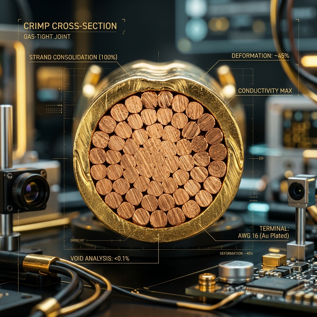
A high-precision terminal crimp is not simply a mechanical squeeze; it is a molecular cold-welding process. During the crimping cycle, massive mechanical pressure is exerted by the crimping die, forcing the copper wire strands and the terminal barrel to deform plastically. Under high pressure, the surface oxides of the metals are sheared and dispersed, allowing clean metal-to-metal atomic contact. This deformation eliminates all voids, resulting in a solid, homogenous mass of copper and terminal alloy with zero internal air pockets. This state is known as a gas-tight seal.
A gas-tight seal is critical because it prevents moisture, atmospheric gases, and corrosive agents from infiltrating the crimp joint. If air pockets remain in the crimp, humidity and temperature fluctuations will cause micro-condensation inside, initiating galvanic corrosion. Within months, this corrosion layer increases the contact resistance of the joint, degrading the voltage pathway. An audit of a crimp cross-section under microscope magnification reveals the exact state of compaction: the individual wire strands should deform from round shapes into interlocking hexagons, leaving no blank areas within the terminal boundary.
Even a perfectly crimped terminal is useless if it is not securely locked into the connector housing. In high-vibration applications, the primary locking lance of the terminal can fail to seat completely due to manufacturing tolerances or operator fatigue, leading to a failure state called terminal back-out. To eliminate this vulnerability, high-reliability connector systems employ secondary lock mechanisms: TPA (Terminal Position Assurance) and CPA (Connector Position Assurance).
A TPA is a physical plastic insert that can only be pushed into the locked position if every single terminal in the connector housing is fully seated in its primary lock. If a terminal is backed out by even 0.2mm, the TPA locking wedge hits the terminal body, blocking the insertion of the TPA and alerting the operator to the defect instantly. Similarly, a CPA is a secondary slide lock on the outer mating housing that prevents the main latch from releasing under violent vibration or external impact. Integrating TPA and CPA geometries guarantees that the physical connection cannot be unseated by anything short of structural destruction.
To eliminate human error and guess-work during the tooling and setup phase of manufacturing, engineers deploy mathematical models to compute the target crimp height. The crimp height is determined by the total cross-sectional area of the wire strands, the terminal wall thickness, and the target compression ratio (typically 15% to 20% area reduction for optimal electrical and mechanical performance). The following Python program computes the target crimp height and deforms the geometry mathematically to simulate the cold-welded state.
This automated computation serves as the primary calibration target for the automated terminal crimping press. By feeding these variables directly into the machine calibration enclaves, we can dynamically compensate for minor differences in material thickness and alloy compositions, guaranteeing absolute repeatability across millions of consecutive termination cycles.
Every wiring assembly produced under the Sovereign Standard must undergo a multi-layered verification audit before being cleared for system integration. There is no room for subjective quality assessments; every interface is either mathematically compliant or rejected. The following inspection protocol is the absolute defense line against systemic failure:
| Checkpoint ID | Technical Variable | Target Threshold / Tolerance | Inspection Method | Consequence of Deviation |
|---|---|---|---|---|
| AUD-01 | Terminal Crimp Height | ±0.02 mm of target calc | Precision Micrometer / Calipers | Galvanic oxidation or strand damage |
| AUD-02 | Wire Strip Length | Nominal length +0.5mm / -0.0mm | Automated Laser Audit / Visual | Exposed copper core or insulation catch |
| AUD-03 | Bellmouth Flare | 0.13 mm to 0.51 mm | Microscope Magnification Audit | Sharp edge shearing of wire strands |
| AUD-04 | Conductor Brush Extension | 0.50 mm to 1.00 mm past crimp | Direct Visual Verification | Incomplete terminal mechanical grip |
| AUD-05 | TPA Engagement | 100% Locked position achieved | Mechanical click & physical pull test | Terminal back-out under vibration |
By enforcing this rigorous audit standard across all physical nodes, we guarantee that the wire harness ceases to be a potential single point of failure. Instead, it becomes an indestructible physical neural network, bridging the gap between raw silicon intelligence and sovereign execution.
Sovereign power is not absolute until it is physically constrained and routed with absolute precision. Let your tools be calibrated daily, your crimp heights measured hourly, and your visual audits executed with zero tolerance. A system that cannot manage its physical connection is a system built on sand.


