[HE#07] Signal Integrity: Maintaining Signal Integrity via CAN and Ethernet under High EMI Entropy
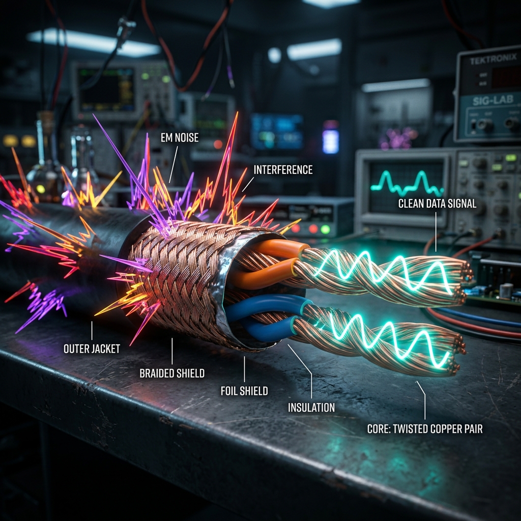
[HE#07] Signal Integrity: Maintaining Signal Integrity via CAN and Ethernet under High EMI Entropy
In high-performance electric vehicles, low-voltage communication wires run alongside high-voltage power conduits carrying hundreds of kilowatts. When high-voltage silicon-carbide (SiC) inverters switch currents rapidly to drive the motors, they generate severe electromagnetic fields. Without defensive measures, this EMI (Electromagnetic Interference) entropy breaches the low-voltage communication lines, corrupting safety-critical steering and braking commands. This chapter details Signal Integrity—how to deploy physical shielding, twisted-pair geometry, and differential mathematics to maintain pristine data loops in extreme noise zones.
Modern electric vehicles are massive mobile electromagnetic emitters. The primary source of signal corruption is the high-voltage motor inverter. As the inverter switches DC battery power to multi-phase AC power, it produces rapid changes in current over time (high dI/dt) and rapid changes in voltage over time (high dV/dt). These swift switching pulses radiate high-frequency electromagnetic noise waves across the entire vehicle body structure.
If low-voltage signaling wires are routed parallel to high-voltage conduits without adequate physical distance or shielding, inductive and capacitive coupling will superimpose noise voltages onto the communication loops. A noise spike exceeding 1.5V on a CAN bus is interpreted by microcontrollers as a corrupted bit, triggering CAN error frames that can drop the vehicle network into an unrecoverable "Bus Off" state.
Defending signal integrity begins with physical geometry and copper routing. Traditional flat wire routings act as perfect loop antennas, absorbing magnetic flux. To counteract this, low-voltage data networks rely on Twisted-Pair (TP) geometry.
By twisting two conductors (like CAN_H and CAN_L) around each other at a precise pitch (e.g. 33 twists per meter), any external magnetic field cuts across both wires in opposite directions. The induced noise voltage in one twist loop perfectly cancels out the induced voltage in the next loop, neutralizing magnetic noise. For high-speed lines, we wrap the twisted pairs inside a grounded metallic braid shield (SF/UTP) to form a Faraday cage, physically deflecting high-frequency electric fields away from the internal copper threads.
Differential signaling is the ultimate mathematical defense against radiated noise. Instead of measuring signal voltage relative to a shared chassis ground (which is noisy), a differential receiver measures the voltage difference between two dedicated lines (V_diff = V_positive - V_negative).
When an electromagnetic noise wave hits a tightly twisted pair, it injects an identical noise voltage (V_noise) onto both wires simultaneously. This is known as common-mode noise. Because the differential receiver subtracts the negative line from the positive line, the common-mode noise is mathematically cancelled out:
V_measured = (V_positive + V_noise) - (V_negative + V_noise) = V_positive - V_negative
This mathematical subtraction yields the pristine, uncorrupted signal. A receiver's ability to successfully cancel out this common-mode noise is quantified as its CMRR (Common-Mode Rejection Ratio). A premium differential receiver must possess a CMRR of 80dB or higher to maintain flawless high-speed communication under severe EMI.
While physical shielding and differential receivers remove the bulk of common-mode EMI, extremely high-frequency noise spikes can still penetrate the physical boundary as transient differential noise. To neutralize these high-speed spikes, microcontrollers deploy logic-level hardware filters.
An analog low-pass RC filter is integrated directly at the receiver input pin to attenuate high-frequency noise above the bus operating speed. Additionally, the microcontroller's digital CAN controller executes bit-level majority voting—sampling each incoming data bit three times at different sub-intervals to filter out transient noise spikes that occur mid-bit, ensuring absolute validation of every bit stream.
| Protocol Standard | Nominal Data Rate | Characteristic Impedance | Termination Configuration | Recommended Physical Shielding |
|---|---|---|---|---|
| Classic CAN 2.0B | 1.0 Mbps | 120 Ω ± 10% | Split termination (2x 60 Ω + 4.7nF) | UTP (Unshielded Twisted Pair) |
| CAN-FD (Flexible Data) | 5.0 Mbps | 120 Ω ± 5% | Split termination with common-mode choke | STP (Shielded Twisted Pair) |
| 100BASE-T1 (Automotive Ethernet) | 100 Mbps | 100 Ω ± 10% | AC-coupled differential termination | UTP / STP (Based on EMI zone class) |
| 1000BASE-T1 (Gigabit Ethernet) | 1.0 Gbps | 100 Ω ± 5% | High-frequency differential balun filter | S/STP (Fully Shielded Twisted Pair) |
To mathematically model how differential signaling cancels out common-mode electromagnetic noise and how CRC checksums catch any residual bit corruption, engineers can simulate a noisy communication channel. The following Python module implements differential subtraction, injects high-frequency EMI spikes, and validates frame integrity.
Running this script proves that even when the electromagnetic noise spike voltage exceeds the signal voltage itself, the mathematical differential subtraction perfectly cancels out the interference, validating why twisted-pair differential routing is the absolute baseline standard of sovereign physical connectivity.
To qualify any high-speed communication network inside an electric or autonomous vehicle, every physical data channel must satisfy the following validation thresholds:
| Checkpoint ID | Signal Integrity Parameter | Target Threshold / Tolerance | Inspection Tool | Failure Consequence |
|---|---|---|---|---|
| STR-21 | Termination Resistance | 120 Ω ± 5 Ω (End-to-End) | Precision Digital Ohmmeter | Signal reflection waves leading to bit corruption |
| STR-22 | Common Mode Rejection | CMRR ≥ 80 dB up to 500 MHz | Vector Network Analyzer (VNA) | Radiated EMI spikes causing network bus-off crashes |
| STR-23 | Jitter & Propagation Delay | Bit-jitter ≤ 15 nanoseconds | High-Frequency Mixed-Signal Oscilloscope | Bit timing synchronization failures and frame drops |
| STR-24 | Shielding Continuity | Shield resistance ≤ 10 mΩ/meter | Four-Point Probe Resistance Meter | Faraday cage leaks and external noise absorption |
| STR-25 | Twist Pitch Uniformity | 33 twists/meter ± 2 twists | Optical Metrology Micrometer | Impedance mismatch zones generating crosstalk |
By strictly enforcing this signal integrity protocol, engineers defend their cyber-physical communications from the extreme noise fields generated by high-power motors and high-voltage grids, achieving sovereign structural and digital resilience.
We refuse to allow noise to compromise our logical states. Let our communications be differential, our wires be precisely twisted, and our shields be continuous. Defending bit-level integrity against high-power inverter switching entropy is the ultimate baseline of physical system security.


