[HE#08] Power Dynamics: Strategic Power Routing for High-Voltage Battery Arrays and Energy Management Systems (EMS)
[HE#08] Power Dynamics: Strategic Power Routing for High-Voltage Battery Arrays and Energy Management Systems (EMS)
In high-power industrial machinery, deep-space vehicles, and elite electric transport networks, the power harness is the primary source of kinetic energy. Unlike low-power signal wires that route logical metrics, the power harness routes hundreds of kilowatts of electric current. Managing this massive current requires an absolute containment protocol. A single short-circuit on a 800V battery pack can vaporize metal instantly, while minor imbalances in cell voltage can degrade pack capacity permanently. This chapter details Power Dynamics—separating high and low voltage domains, solid busbar design, precharge architectures, and Energy Management System (EMS) control loops.
In high-voltage architectures, we establish an absolute, non-negotiable physical firewall between high-voltage power domains (e.g. 400V/800V powertrains) and low-voltage control domains (e.g. 12V/48V microcontrollers). This physical barrier is known as galvanic isolation.
This barrier prevents high-voltage transient noise from corrupting low-voltage computing circuits, ensuring that even in the event of an insulation rupture, hazardous high-voltage cannot reach passenger compartments or computational logic chips.
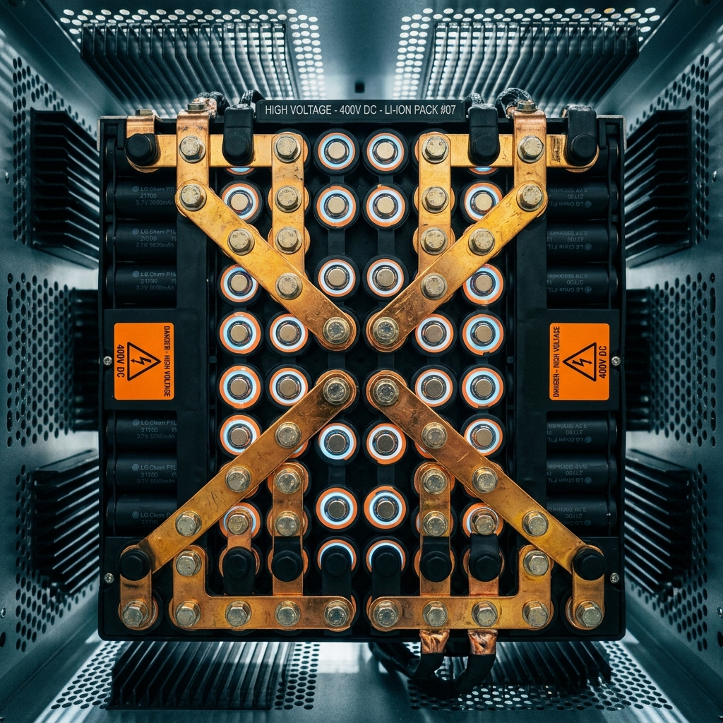
When routing currents upwards of 500 Amperes, standard circular copper wire cables become impractical. They require massive cross-sections, adding prohibitive weight and taking up excessive space. To solve this, engineers deploy solid metal busbars—flat copper or aluminum plates.
Flat busbars have a much higher surface-area-to-volume ratio than round cables, significantly enhancing convective thermal dissipation. Additionally, solid busbars completely eliminate mechanical flexing, which prevents wire fatigue and packaging wear inside high-vibration battery compartments. To prevent galvanic corrosion, these busbars are nickel-plated or gold-plated and bolted to battery terminals with precise torque protocols to minimize contact resistance.
A high-voltage battery array is composed of thousands of individual lithium-ion cells connected in series and parallel. To prevent individual cells from overcharging (which causes thermal runaway) or over-discharging (which permanently destroys the chemistry), we establish an Energy Management System (EMS).
The EMS acts as a neural sensor network. Ultra-fine low-voltage wire harnesses tap into the junction of every series cell connection to measure voltage, while thermistor networks monitor temperatures. Because these microvolt sensing lines are physically connected to high-voltage cell terminals, they must immediately pass through highly isolated analog-front-end (AFE) chips to convert voltages to digital signals before crossing the galvanic isolation barrier to the central computer.
Safely energizing a high-voltage power system requires a strategic startup sequence. Motor inverters contain massive input capacitor banks. If we close the main battery contactors (heavy magnetic switches) directly, the empty capacitors will draw thousands of amperes of inrush current in a fraction of a millisecond. This inrush current creates a high-energy arc that can physically weld the contactor terminals shut, rendering the emergency cutoff system useless.
To prevent welding contactors, we design a precharge circuit. The precharge circuit consists of a small relay and a high-power resistor connected in parallel with the main positive contactor. During startup, the precharge relay closes first, routing battery power slowly through the resistor to charge the inverter capacitors to 95% of battery voltage. Once this voltage is stabilized, the main positive contactor closes with zero arcing, and the precharge relay safely opens.
| Subsystem Component | Primary Safety Mandate | Target Threshold / Limit | Physical Verification Method | Failure Leak Consequence |
|---|---|---|---|---|
| Main Contactors | Isolate high voltage battery under load | Break capacity ≥ 2,000 Amps | Magnetic coil state feed-back loop | Contacts weld shut; unable to isolate battery |
| Precharge Resistor | Limit inverter capacitive inrush current | Limit peak inrush to ≤ 10 Amps | Dual-phase voltage drop comparison | Severe electric arcing welds main contacts |
| Galvanic Isolation | Separate high power from low power | Dielectric strength ≥ 5,000 Vrms | Hi-Pot isolation resistance check | 800V leaks to 12V logic, vaporizing computer |
| Pyrotechnic Fuse | Millisecond-level safety fault isolation | Trigger cutoff time ≤ 3 milliseconds | Programmatic current trigger sensor | Explosive thermal runaway inside battery cells |
To model how an EMS monitors individual cell voltages, tracks temperatures, and automatically triggers passive cell shunting (cell balancing) to keep the pack uniform and prevent thermal failure, engineers can execute a control simulation.
Executing this control algorithm demonstrates how the EMS acts as a digital supervisor, keeping individual battery voltages balanced within narrow tolerances to guarantee maximum energy capacity and ensure total system longevity.
To successfully certify any high-voltage battery array or energy distribution system, the integration must satisfy the following galvanic and physical parameters:
| Checkpoint ID | Power Dynamics Parameter | Target Threshold / Tolerance | Verification Method | Failure Consequence |
|---|---|---|---|---|
| STR-26 | Galvanic Isolation Resistance | ≥ 500 MΩ at 1,000 VDC | High-Voltage Megohmmeter (Hi-Pot) | Dangerous electric shock to low-voltage computer |
| STR-27 | Precharge Voltage Match | Contactor closes only at ≥ 95% charge | Analog comparator delta differential check | Welded contactor contacts and relay damage |
| STR-28 | Clearance & Creepage Limits | ≥ 8.0 mm creepage at 800 VDC | Optical digital mechanical metrology caliper | Surface voltage arcing and dielectric breakdown |
| STR-29 | Bolted Joint Torquing | 9.0 Nm ± 0.5 Nm (Nickel plated M6) | Digital torque wrench with logging | High joint resistance generating thermal hot spots |
| STR-30 | Thermal Ingress Threshold | Initiate load de-rating at ≥ 55°C | Isolated analog thermistor calibration audit | Catastrophic cell thermal runaway and combustion |
By enforcing this power dynamics validation checklist, our power infrastructures achieve sovereign structural security, making high-voltage arrays and EMS nodes completely immune to catastrophic failures and thermal entropy.
We refuse to allow electrical entropy to compromise our power grids. Let our isolation barriers be absolute, our busbars be solid, and our safety relays be meticulously timed. Securing high-voltage power dynamics against insulation failures is the ultimate standard of physical energy management.
We refuse to allow electrical entropy to compromise our power grids. Let our isolation barriers be absolute, our busbars be solid, and our safety relays be meticulously timed. Securing high-voltage power dynamics against insulation failures is the ultimate standard of physical energy management.


